Synchronous Mode 3: Manual Dial with Data/Talk Switch &Q3
In synchronous mode 3, the DTR interchange circuit is a data/talk switch.
This mode supports a synchronous-only DTE or a PC with a synchronous adapter
card installed. A telephone set must be attached to the PHONE connector
on the modem or directly to the telephone line. This mode permits the DTE
operator to place a call on the phone with the modem in talk mode, and to
complete the call by switching the modem to the data mode by turning on
the DTR interchange circuit. When configuring the modem for this mode, turn
off result codes with the Q1 command. The modem can be configured in the
asynchronous command state while &Q3 is in effect, but the D and A commands
are disabled.
To originate a call in synchronous mode 3, the DTR interchange circuit must
be off. This places the modem in talk mode. When the modem is configured
for this mode with the &Q3 command, the terminal operator can lift the receiver
and dial the number. When the last character of the dial string is dialed,
the modem can be switched to data mode by causing the DTE to turn on the
DTR signal. The operator should then hang up the receiver. When the data
terminal equipment turns on DTR, the TR indicator (on the front panel of
external Smartmodem and V-series products) lights up. For the responses
associated with transitions of the DTR signal for this mode, refer to the
discussions of the &D command.
The modem exits the synchronous online state and returns to the asynchronous
command state when a loss of carrier exceeding the time interval stored
in S10 is detected.
The following diagram depicts modem operation in synchronous mode 3:
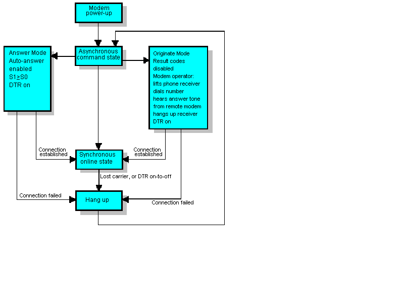
If the connection fails, the modem automatically hangs up and switches from
data to talk mode. To re-initiate the call, DTR must again be turned off.