


 User's Guide
PART 2. Relational Database Concepts
CHAPTER 13. Designing Your Database
In designing a database, you plan what things you want to store information about, and what information you will keep about each one. You also determine how these things are related. In the common language of database design, what you are creating during this step is a conceptual database model.
The distinguishable objects or things that you want to store information about are called entities. The associations between them are called relationships. You might like to think of the entities as nouns in the language of database description and the relationships as verbs.
Conceptual models are useful because they make a clean distinction between the entities and relationships. These models hide the details involved in implementing a design in any particular database management system. They allow you to focus on fundamental database structure. Hence, they also form a common language for the discussion of database design.
The main component of a conceptual database model is a diagram that shows the entities and relationships. This diagram is commonly called an entity-relationship diagram. In consequence, many people use the name entity-relationship modeling to refer to the task of creating a conceptual database model.
Conceptual database design is a top-down design method. There are now sophisticated tools such as Powersoft PowerDesigner that helps you pursue this method, or other approaches. This chapter is an introductory chapter only, but it does contain enough information for the design of straightforward databases.
 Entities
An entity is the database equivalent of a noun. Distinguishable objects such as employees, order items, departments and products are all examples of entities. In a database, a table represents each entity. The entities that you build into your database arise from the activities for which you will be using the database, whether that be tracking sales calls, maintaining employee information, or some other activity.
Each entity contains a number of attributes. Attributes are particular characteristics of the things that you would like to store. For example, in an employee entity, you might want to store an employee ID number, first and last names, an address, and other particular information that pertains to a particular employee. Attributes are also known as properties.
You depict an entity using a rectangular box. Inside, you list the attributes associated with than entity.
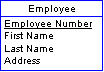
An identifier is one or more attributes on which all the other attributes depend. It uniquely identifies an item in the entity. Underline the names of attributes that you wish to form part of an identifier.
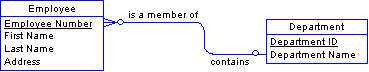
In the Employee entity, above, the Employee Number uniquely identifies an employee. All the other attributes store information that pertains only to that one employee. For example, an employee number uniquely determines an employee's name and address. Two employees might have the same name or the same address, but you can make sure that they don't have the same employee number. Employee Number is underlined to show that it is an identifier.
It is good practice to create an identifier for each entity. As will be explained later, these identifiers become primary keys within your tables. Primary key values must be unique and cannot be null or undefined. They identify each row in a table uniquely and improve the performance of the database server.
RelationshipsA relationship between entities is the database equivalent of a verb. An employee is a member of a department, or an office is located in a city. Relationships in a database may appear as foreign key relationships between tables, or may appear as separate tables themselves. You will see examples of each in this chapter.
The relationships in the database are an encoding of rules or practices that govern the data in the entities. If each department has one department head, you can create a one-to-one relationship between departments and employees to identify the department head.
Once a relationship is built into the structure of the database, there is no provision for exceptions. There is nowhere to put a second department head. Duplicating the department entry would involve duplicating the department ID, which is the identifier. Duplicate identifiers are not allowed.
Tip |
There are three kinds of relationships between tables. These correspond to the cardinality (number) of the entities involved in the relationship.
One-to-one relationships You depict a relationship by drawing a line between two entities. The line may have other markings on it such as the two little circles shown. Later sections explain the purpose of these marks.
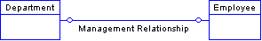
One employee manages one department.
One-to-many relationships The fact that one item contained in Entity 1 can be associated with multiple entities in Entity 2 is denoted by the multiple lines forming the attachment to Entity 2.
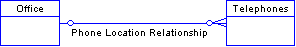
One office can have many telephones.
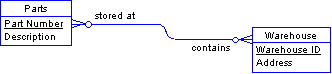
Many-to-many relationships In this case, draw multiple lines for the connections to both entities.
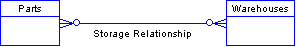
One warehouse can hold many different parts and one type of part can be stored at many warehouses.
You can describe each relationship with two roles. Roles are verbs or phrases that describe the relationship from each point of view. For example, a relationship between employees and departments might be described by the following two roles.
An employee is a member of a department.
A department contains an employee.
Roles are very important because they afford you a convenient and effective means of verifying your work.
Tip |
The little circles just before the end of the line that denotes the relation serve an important purpose. A circle means that an element can exist in the one entity without a corresponding element in the other entity.
If a cross bar appears in place of the circle, that entity must contain at least one element for each element in the other entity. An example will clarify these statements.
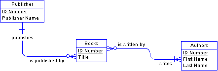
This diagram corresponds to the following four statements.
A publisher publishes zero or more books.
A book is published by exactly one publisher.
A book is written by one or more authors.
An author writes zero or more books.
Tip |
Sometimes, a relationship will exist between entries in a single entity. In this case, the relationship is called reflexive. Both ends of the relationship attach to a single entity.
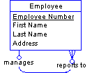
This diagram corresponds to the following two statements.
An employee reports to at most one other employee.
An employee manages zero or more or more employees.
Notice that in the case of this relation, it is essential that the relation be optional in both directions. Some employees are not managers. Similarly, at least one employee should head the organization and hence report to no one.
 Naturally, you would also like to specify that an employee cannot be his or her own manager. This restriction is a type of business rule. Business rules are discussed later as part of The design process.
Changing many-to-many relationships into entitiesWhen you have attributes associated with a relationship, rather than an entity, you can change the relationship into an entity. This situation sometimes arises with many-to-many relationships, when you have attributes that are particular to the relationship and so you cannot reasonably add them to either entity.
Suppose that your parts inventory is located at a number of different warehouses. You have drawn the following diagram.
But you wish to record the quantity of each part stored at each location. This attribute can only be associated with the relationship. Each quantity depends on both the parts and the warehouse involved. To represent this situation, you can redraw the diagram as follows:
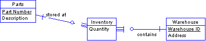
Notice the following details of the transformation:
Two new relations join the relation entity with each of the two original entities. They inherit their names from the two roles of the original relationship: stored at and contains, respectively.
Each entry in the Inventory entity demands one mandatory entry in the Parts entity and one mandatory entry in the Warehouse entity. These relationships are mandatory because a storage relationship only makes sense if it is associated with one particular part and one particular warehouse.
The new entity is dependent on both the Parts entity and on the Warehouse entity, meaning that the new entity is identified by the identifiers of both of these entities. In this new diagram, one identifier from the Parts entity and one identifier from the Warehouse entity uniquely identify an entry in the Inventory entity. The triangles that appear between the circles and the multiple lines that join the two new relationships to the new Inventory entity denote the dependencies.
Do not add either a Part Number or Warehouse ID attribute to the Inventory entity. Each entry in the Inventory entity does depend on both a particular part and a particular warehouse, but the triangles denote this dependence more clearly.